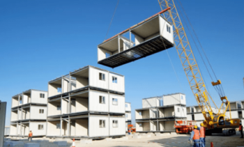
Basic Modular Construction
Modular Buildings are fabricated and put together with individual modules. When assembled on-site the finished modules create and make up the complete modular building. Factories that build the individual modules will have their very own design to suit their factory set-up. If you research all the different manufacturer’s designs, you will notice that all will have different construction arrangements and details. This is because manufacturers have their very own design, but also, they will have to design one-off projects that will be required to suit individual project specifications and budget constraints.
Although the individual modules will differ, modular manufacturers follow a basic design covering the steel frame and the building envelope. The following basic design will cover the std modular system, i.e., multi stacking, three walls if a gable bay and two walls if an immediate bay, roof and floor, rather than the fully portable unit, four walls etc.
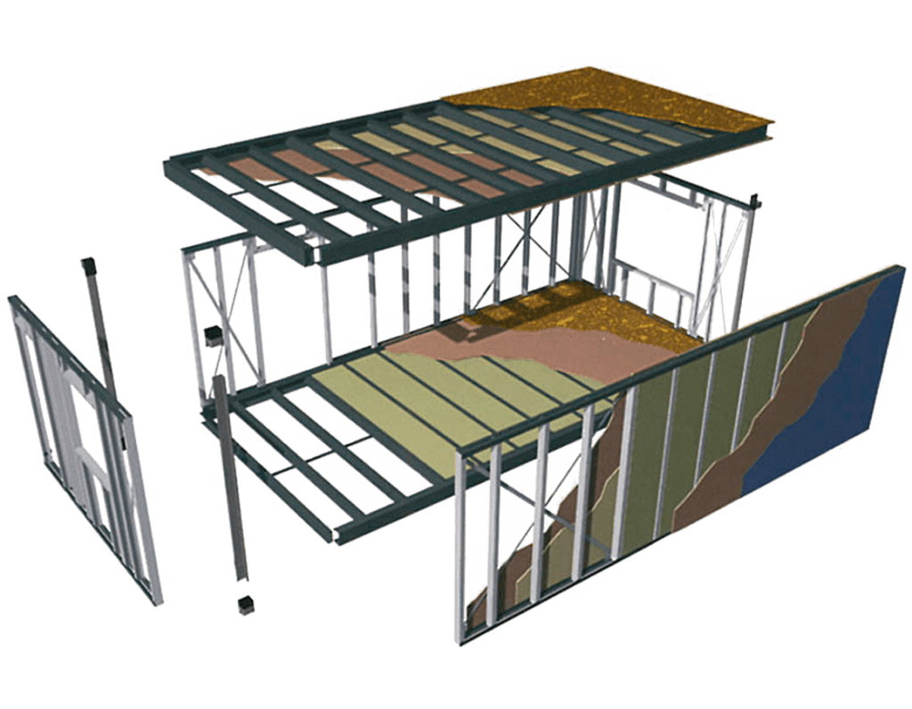
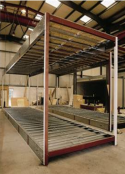
Steel Frame – Open-sided (corner supported)
The standard modular steel frame consists of a roof, floor and corner posts. The module structure creates the basic design of the frame and the structural strength of each bay. The make-up of the roof, floor and walls will provide further structural integrity.
Modular Roof Design
The modular roof design within the steel frame is designed in various ways. One of the most common is that of the C Channel design. This design includes two roof beams that span the full length of the module. Typically, these lengths will start @ 6.0m up to 14.0m. The depth of the C channel can range from 100mm deep, up to 450mm deep. As we can appreciate this depth of the main roof beam will depend on the overall design of the modular project. The other dimension is the width of the roof beam, this will alter, but 100mm is a typical width. The depth of the inner lip to form the final part of the C Channel design will be approximal 25mm deep. The roof beam has two roof end beams, normally covering the above sizes, or slightly smaller. This will complete the outer frame of the roof.
The type of steel used for the roof construction is pre-galvanised, ranging from 2.5mm to 5mm. pre-galvanised, meaning, occurred at the mills, and the results of the process will be cut into size and fabricated later. This is supposed to hot-dipped galvanised process.
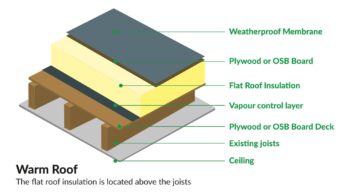
A warm roof deck construction is a popular design for a C Channel frame system. A warm roof is a type of roof construction that has an insulation layer above the steel roof joists and immediately below its weatherproof membrane. This allows heat to be conserved within the building without the need for a ventilation system. The cold roof system is still used, but the warm roof can give a quick construction method and in general, is a more preferred design.
The build-up of the roof can have various construction designs. The most practical is an insulated sandwich panel design, consisting of 100mm PIR insulation, placed between two sheets of 11mm roofing plywood. The outer roof covering is normally a single layer roofing membrane.
A practical application for the steel roof joists would be 150mm x 50mm x 17mm x 2mm. Roof joists would be designed at various centres covering anything from 400mm up to 1200mm centres.
Modular Floor Design.
The modular floor design is based on the same principle as the roof design. 2No floor beams will span the full length of the module, and the depth of the floor beams can range from 100mm up to 300mm, once again, depending on the overall design specification.
The floor joists are designed in the same way as the roof design, typically rivetted cleat floor joists 150mm x 50mm x 2mm. The floor joist centres will differ to each specification but are generally designed @ 400mm or 600mm centres. Standard modules bays will have an approx. floor loading of between 3 and 5 (Kn/m2).
The floor construction will include a 9mm to 15mm moisture resistant T&G flooring board complete with floor insulation. Dependant to the design and specification this may be designed with a 100mm PIR insulation board, insulated silver foil wrap, laid over the floor joists and under the flooring plywood or traditional glass wool (glass fibre insulation), this design may need the flooring to underdrawn.
Modular Walling Design
The most common walling to a module structure is timber and or steel framing. The basic design will consist of a bottom soleplate that is fixed to the top of the flooring plywood and also a top rail. The wall panels are complete with uprights. The uprights centres are normally @ 400mm or 600mm.
The timber walling sizes can cover a large variance and is subject to the final design specification, anything from 100mm x 38mm, upwards. Insulation is placed into the walling structure between the uprights, normally 100mm PIR insulation or 100mm glass wool insulation.
Steel wall framing is generally supplied into two sizes and is designed with a top and bottom rail track complete with upright stud, similar to the timber design. Sections are supplied in two standard widths of 75mm and 100mm. Gauges for the 75mm section comprise 1.0, 1.2 and 1.5mm. Gauges for the 100mm section comprise 1.2, 1.5 and 2.0mm (2mm from a lesser yield). These sizes can change if required due to the overall design specification.
The internal walling consists of a 12.5mm vinyl faced plasterboard complete with plastic H sections at the wallboard joints. Top and bottom two-part clip in cornice. Again, we can appreciate that the internal wall ling will have various alternatives, subject to the design specification.
Some of the other most common will be, taped edged plasterboard to receive a tape and fill plaster wall finish for a paint decoration. Alternative to plasterboard maybe, high impact boarding, sound insulation boarding or even double layer plasterboard if any specific fire ratings are required. The wall construction is normally non-load bearing as the whole structure is supported by the four corner posts.
Modular Corner Posts
The modular corner posts provide compression resistance and are typically 100 x 100 SHS members. The general design for a corner post arrangement is typically no more than three stories high. Due to the competitive nature of the industry, some manufacturers will replace the corner posts with flat bars or flitch plates. This is a simple flat bar with a top and bottom plate that are positioned and fixed into the top and bottoms C Channels beams. These are normally only designed for single storey modular buildings rather than multi stacking complexes.
Visited 442 Times, 1 Visit today